
Integrated functional prototype with frozen v1.6.5 firmware and supporting report.
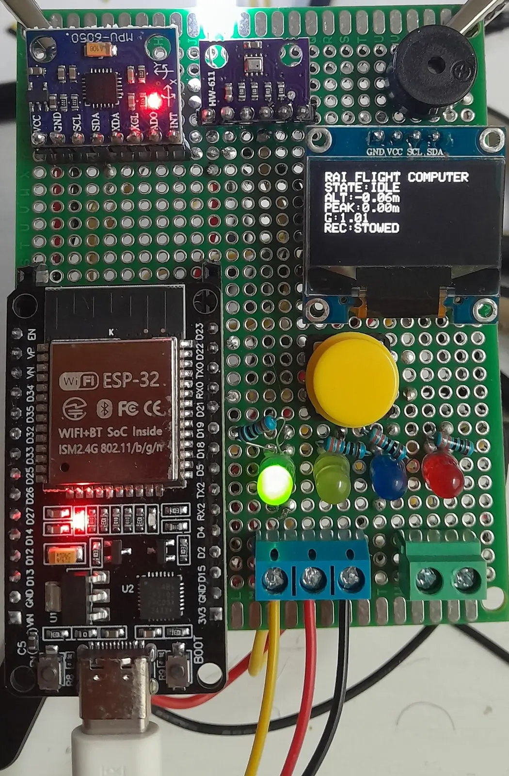
RAI-AVN-001 · INTEGRATED FUNCTIONAL PROTOTYPE
FLIGHT
COMPUTER V1
ESP32 avionics · Deterministic state logic · Bench verifiedInspect engineering record ↓Validation boundaryBench tested · Not flight tested
PROJECT OVERVIEW
A complete bench prototype—
not flight-qualified avionics.
RAI_FC_V1 integrates sensing, embedded logic, human arming, indicators, an actuator output and recovery-beacon behaviour on a hand-built perfboard prototype. Five documented end-to-end bench sequences were completed. The work demonstrates functional integration under controlled conditions; it does not establish flight performance, reliability or airworthiness.
BMP280 pressure sensing, MPU6050 inertial sensing and SSD1306 OLED over I²C.
Five repeated complete state sequences are reported as passing on the bench.
No real flight, vibration, environmental, EMI or high-dynamic qualification.
01 / REAL PROJECT MEDIA
Prototype & development record
01 / 09Final integrated prototype · component side
02 / SYSTEM ARCHITECTURE
Sensor inputs to deterministic outputs.
The architecture drawings describe the actual integrated bench prototype. They are implementation records, not certification drawings.
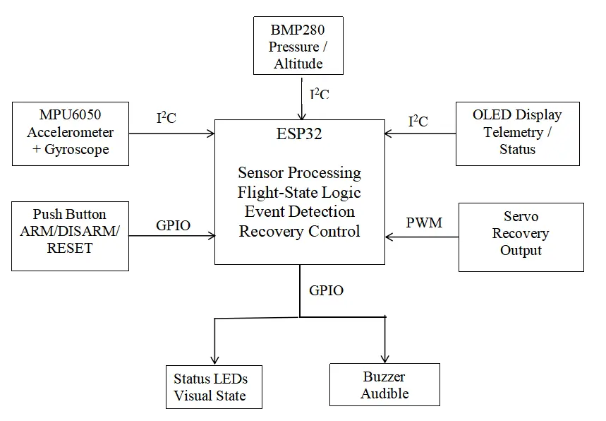
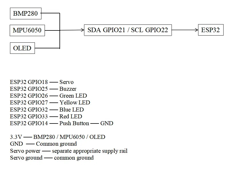
BMP280 + MPU6050
Barometric pressure and six-axis inertial modules provide the measurements used by the event logic.
ESP32
The controller samples sensors, filters altitude, evaluates state transitions and drives outputs.
OLED + LEDs + buzzer
Local indication exposes status and state during controlled bench operation.
SG90 servo
A servo represents the recovery-actuation interface. No parachute deployment was performed.
03 / FROZEN FIRMWARE
v1.6.5 · Button integrated
The published source is the final reported FC_V1 revision. Thresholds below are transcribed from that file, not from the incomplete threshold-document template.
01BOOT
02SELF TEST
03CALIBRATION
04IDLE
05ARMED
06ASCENT
07APOGEE
08DESCENT
09LANDED
These constants were selected for repeatable hand-motion and pressure-change bench demonstrations. They are not validated flight thresholds and should not be transferred to a vehicle without a new requirements, modelling and test process.
04 / BENCH VALIDATION
One complete simulated state sequence.
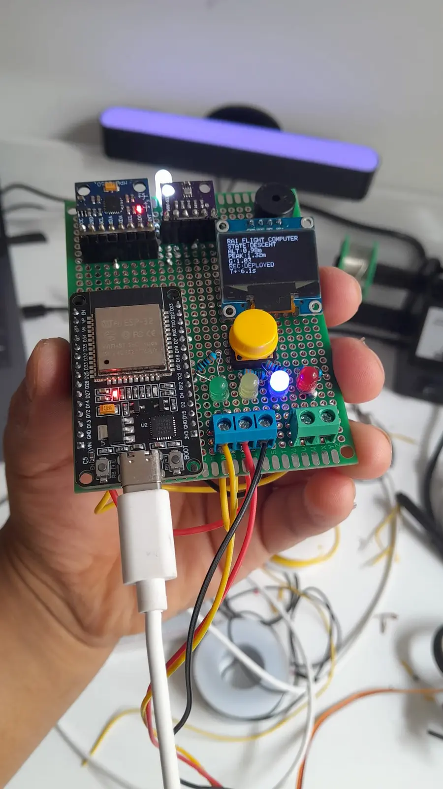
These are photographs of a controlled bench demonstration. Labels such as ASCENT, APOGEE and DESCENT describe firmware states exercised by hand movement and pressure change—not an aircraft or rocket flight.
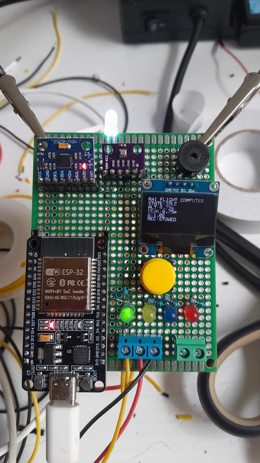
System ready after self-test and calibration
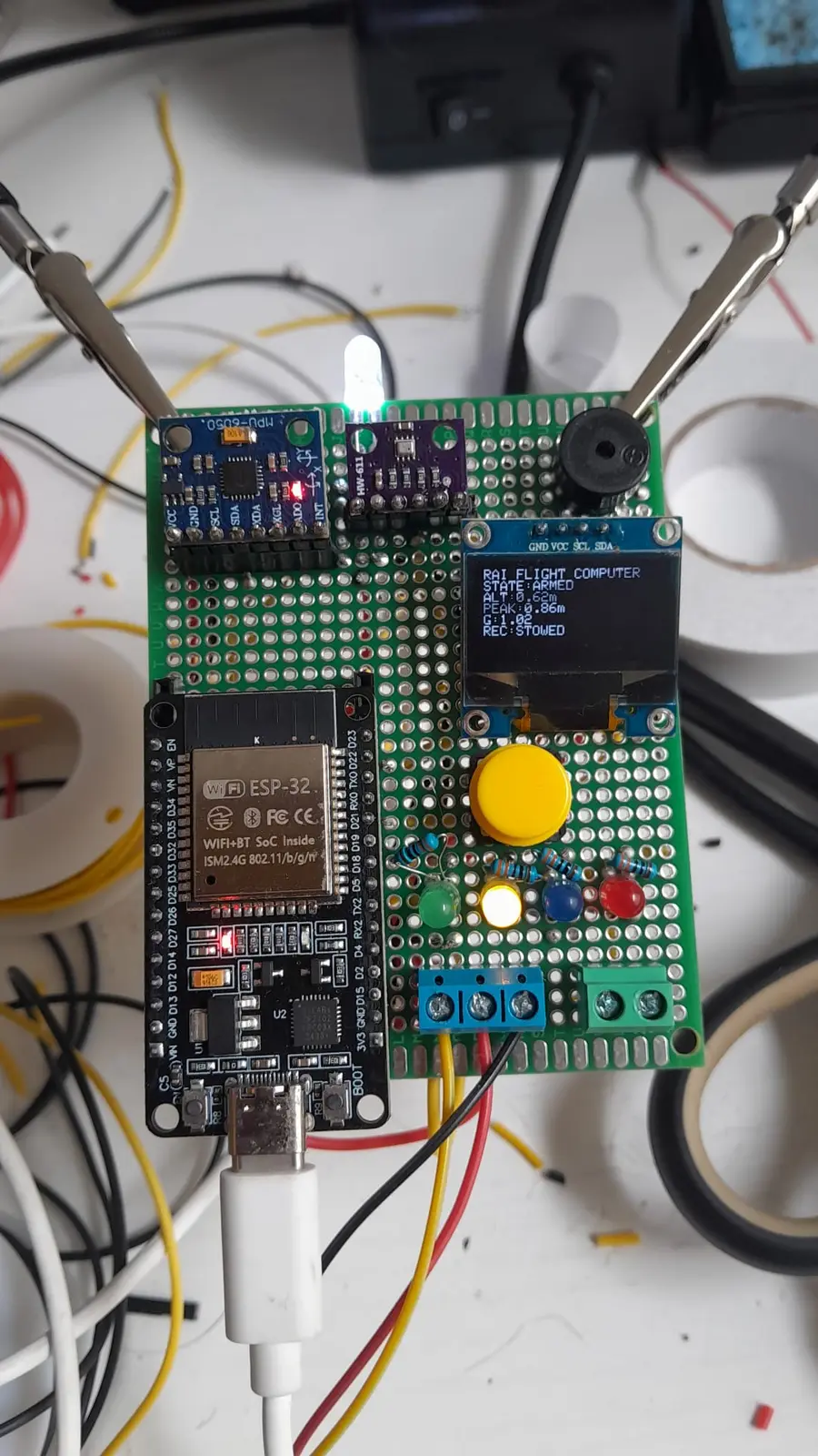
Two-second button hold commands arming
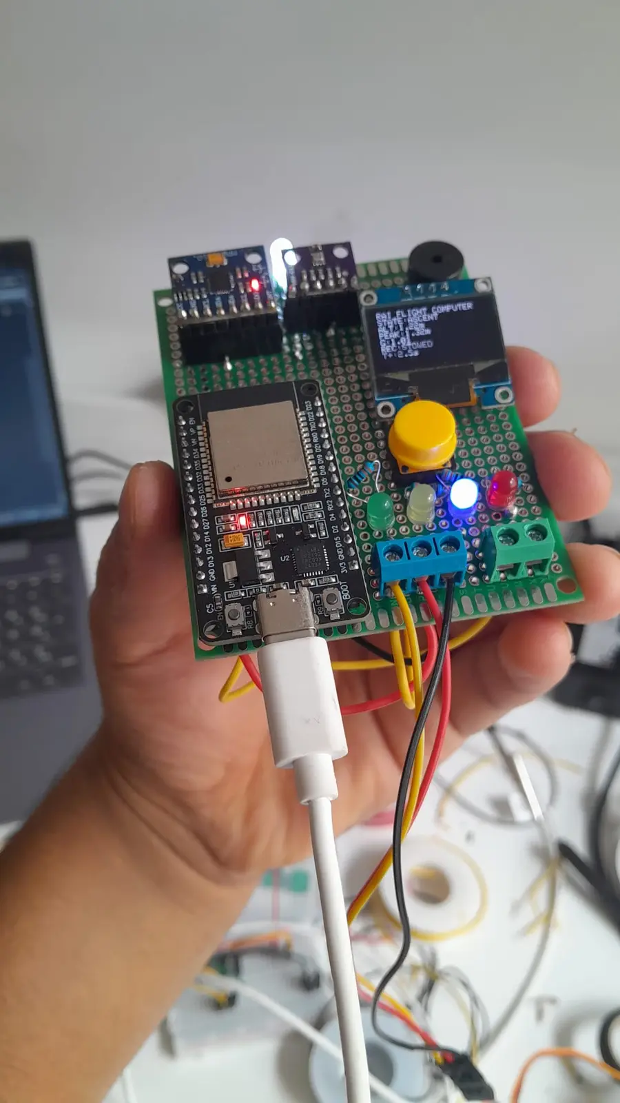
Hand motion and pressure change exercise launch logic
Bench sequence commands the recovery servo
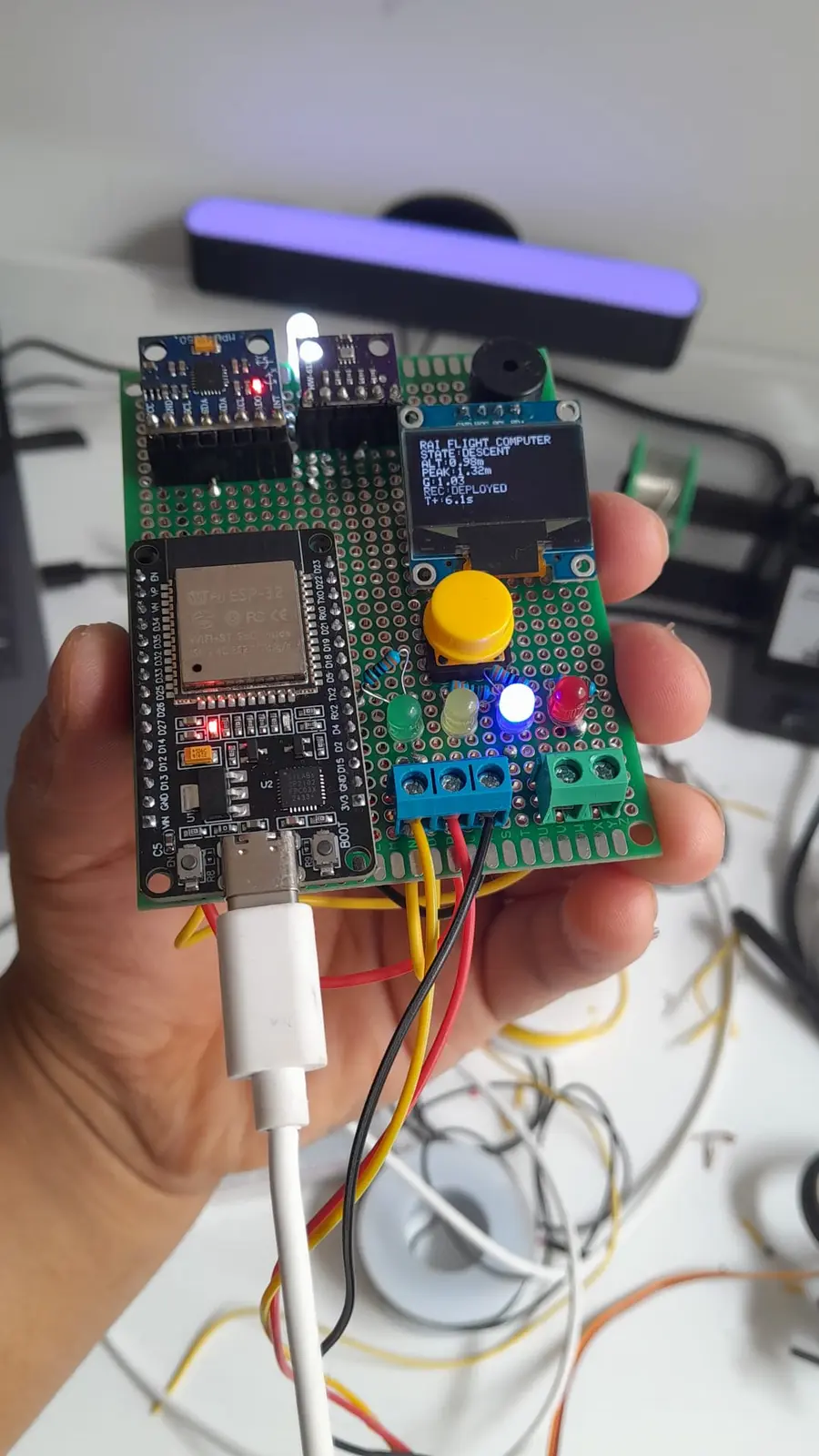
Simulated descent exercises persistence logic
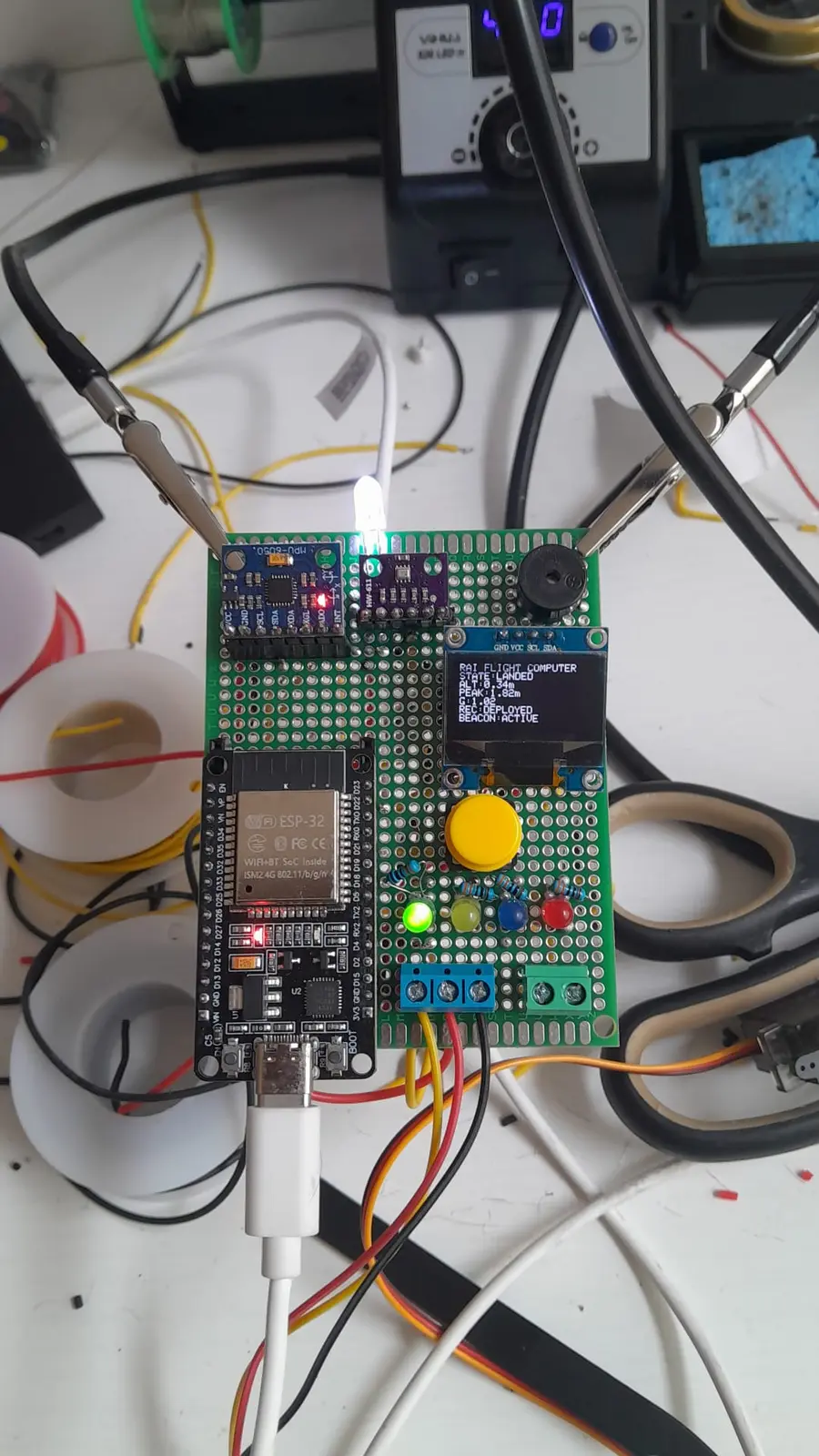
Stable conditions trigger the recovery beacon
5 / 5
Repeated full bench sequences reported as passed
The supplied 75-page report documents five end-to-end runs through the event sequence. The released evidence does not include independent verification, raw time-series logs or flight data.
05 / CURRENT LIMITATIONS
What remains unproven.
- No real flight or launch test has been performed.
- No vibration, shock, thermal, humidity, EMI/EMC or vacuum testing.
- No redundant sensing, power architecture or independent deployment channel.
- No released PCB, enclosure or production-manufacturing process.
- No calibrated altitude-accuracy, drift or uncertainty dataset.
- No SD-card flight logging or published raw bench telemetry.
- The threshold-and-parameters document contains unfinished placeholders.
- Not certified, flight-qualified or intended for operational use.
06 / TECHNICAL RECORD
Inspect the evidence directly.
Reports, firmware, hardware documentation and project governance files are provided as the evidence behind the claims on this page.
75-page PDFFunctional prototype & bench validation report↓Arduino sourceFrozen firmware v1.6.5↓Revision source · ZIPFirmware development archive↓PDFHardware architecture↓PDFWiring diagram↓TXTBill of materials↓TXTPinout↓TXTFirmware revision history↓TXTState-machine documentation↓TXTThreshold document — incomplete draft↓KICAD_SYMKiCad symbol library↓TXTProject README↓TXTCitation information↓TXTLicence↓TXTThird-party notice↓
The threshold document is deliberately marked as an incomplete draft because it still contains placeholder fields. The final source file remains the authoritative record of the bench configuration. Development firmware is supplied for traceability and may include superseded or experimental logic.
07 / NEXT ITERATION
Move from bench function to instrumented validation.
The next credible work is a purpose-designed PCB and power architecture, calibrated sensor characterization, onboard logging, fault-injection tests, vibration and environmental testing, followed by controlled ground and flight testing under an appropriate safety and regulatory framework.
View RAI roadmap →