
CAD assembly, engineering report and preliminary analysis package released.
RAI-PROP-001 · COMPLETED CONCEPTUAL ENGINEERING STUDY
TURBOFAN
ENGINE V1
Two-spool architecture · CAD assembly · Preliminary cycle modelInspect engineering record ↓Evidence availableCAD renders · Octave scripts · Inputs · Report
PROJECT OVERVIEW
A propulsion study—
not a working engine.
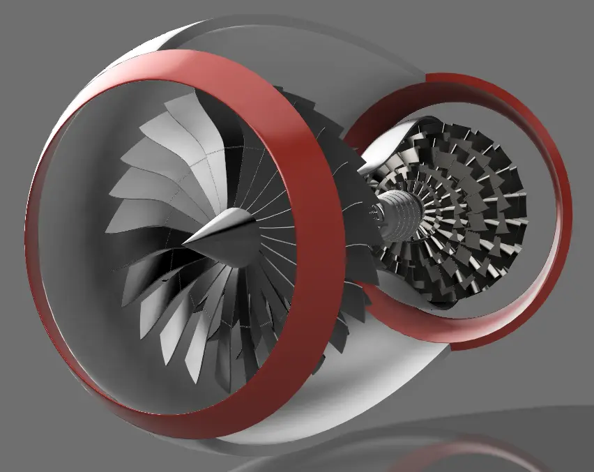
Turbofan Engine V1 combines a detailed Fusion 360 assembly with a preliminary one-dimensional thermodynamic model. The work explores component architecture, flow-path packaging, cycle calculations and technical documentation. It was not manufactured, experimentally tested, calibrated against an existing engine or assessed for certification.
Fan, compressor, combustor, HPT, LPT, shafts, nacelle and separate exhaust streams.
Nine calculation stages using prescribed inputs and fixed component assumptions.
No hardware, rig test, CFD, FEA, rotor dynamics, thermal or acoustic validation.
01 / REAL PROJECT MEDIA
CAD evidence
01 / 08Final CAD configuration · front isometric
02 / ARCHITECTURE
One assembly.
Two mechanical spools.
Fan & bypass duct
The front fan and surrounding duct establish the high-bypass arrangement. The CAD communicates architecture; blade aerodynamics and duct losses are not resolved.
Multi-stage compressor
Axial stages represent the high-pressure compression system. Stage loading, maps, surge margin, clearances and Reynolds effects remain outside this study.
Annular combustor concept
The chamber connects compressor and turbine regions geometrically. Combustion, emissions, liner cooling and pattern factor were not simulated.
HPT & LPT assemblies
Concentric shafts communicate the two-spool power path. Blade stress, cooling, modal behaviour and shaft dynamics remain unverified.
03 / PRELIMINARY THERMODYNAMICS
Assumption-driven model outputs.
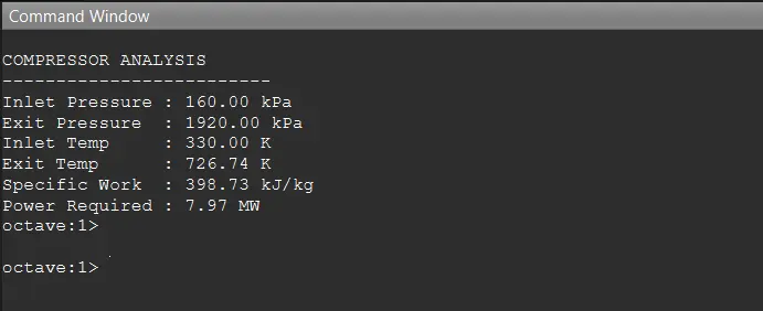
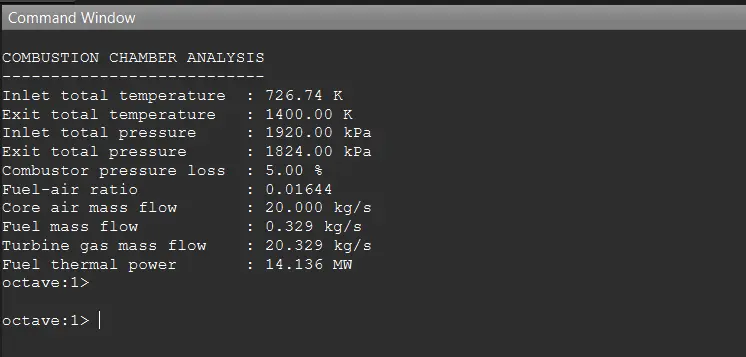
These values reproduce the supplied calculation package. They are model outputs under the listed assumptions—not measured engine performance, design guarantees or validated predictions.
Model boundary
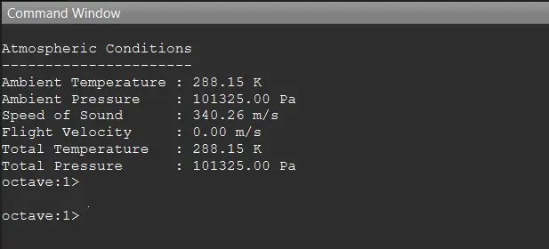
Static sea level; one-dimensional steady flow; ideal gas; constant specific heats; fixed component efficiencies; complete combustion; no cooling-air extraction; negligible leakage; and perfectly expanded nozzles where applicable.
04 / CALCULATION CHAIN
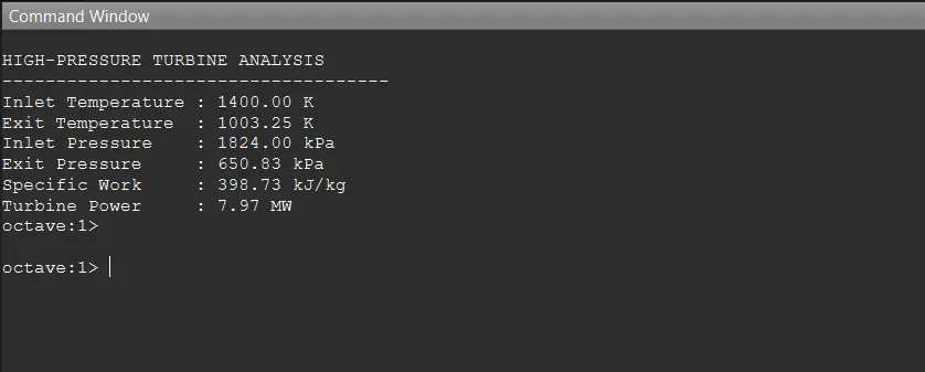
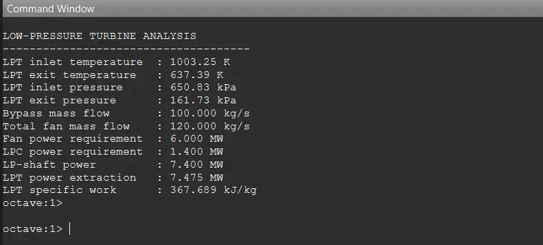
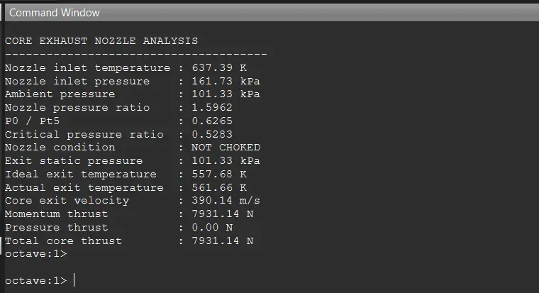
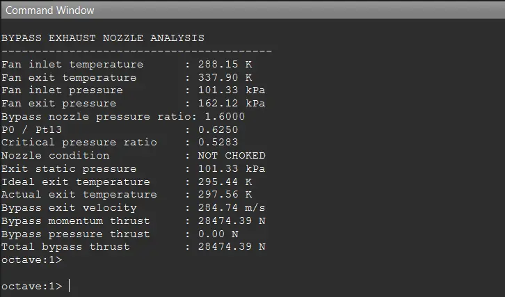
Nine calculation stages
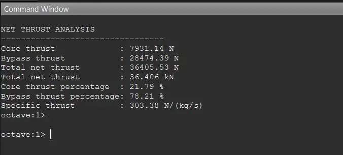
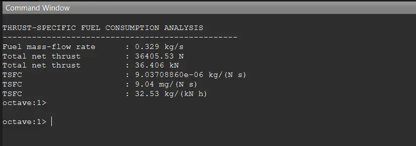
The screenshots below are the actual console outputs supplied with the GNU Octave source. Download the scripts to inspect the equations and fixed inputs directly.
05 / DEVELOPMENT RECORD
The model behind the renders.
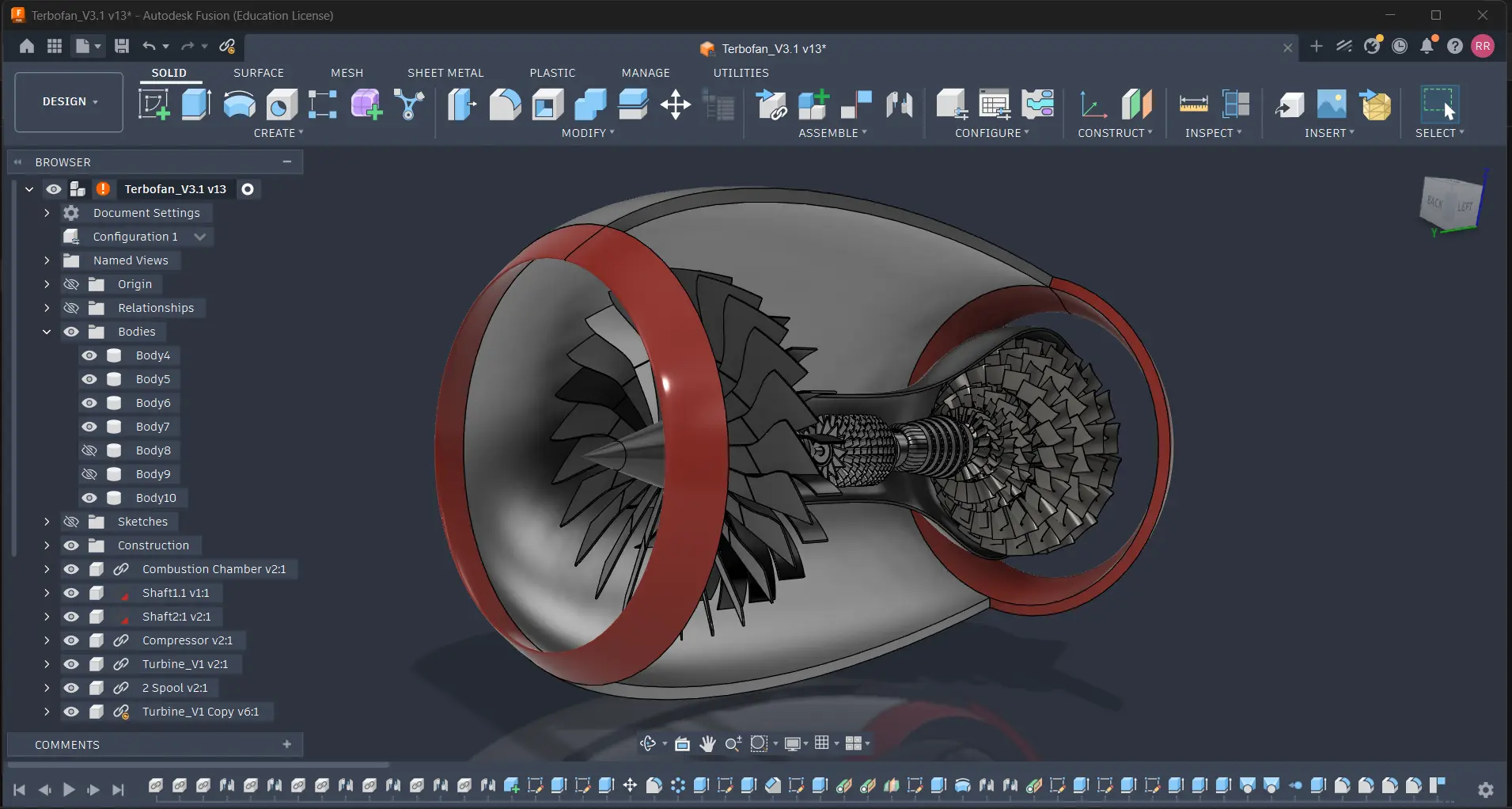
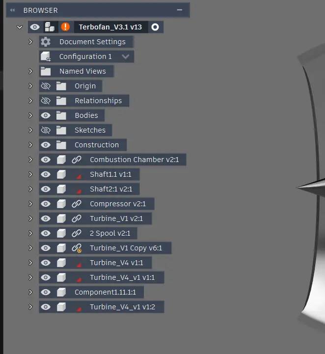
These Fusion 360 captures show the actual project workspace, component tree and assembly state. They provide stronger evidence than a polished render alone, while still not proving manufacturability.
06 / ENGINEERING REVIEW
What must be reconciled before stronger claims.
- The HPT efficiency and pressure-relation implementation requires an independent equation review.
- The results summary labels 20.329 kg/s as core mass flow; the scripts use 20.0 kg/s core air plus 0.329 kg/s fuel.
- Mass flow and component work values are prescribed rather than derived from the released CAD geometry.
- No component maps, off-design analysis, cooling bleed, installation losses or uncertainty study are included.
- Nozzle geometry and pressure thrust are not resolved for a general choked operating case.
- Reported thrust and TSFC therefore remain preliminary outputs, not validated engine specifications.
07 / TECHNICAL RECORD
Reports, inputs and source code
117-page PDFEngineering design report↓3-page PDFEngine input data↓2-page PDFThermodynamic results summary↓9 scripts · ZIPGNU Octave analysis↓TXTProject overview↓TXTProject roadmap↓TXTTechnical specifications↓TXTProject README↓TXTDocumentation index↓TXTLicence↓TXTCitation information↓
The supplementary overview, roadmap and specification files are published as project records. Their “completed” labels mean the preliminary study package was completed—not that the thermodynamic outputs were independently validated. The large native F3Z, STEP and STL source files are preserved in the project archive but are not served here because of deployment-size limits. The citation file still contains a placeholder repository URL, so no GitHub link is published until a verified repository address is supplied.
08 / NEXT ITERATION
Turn the study into a traceable cycle model.
The next credible step is to correct and independently cross-check the cycle equations, reconcile mass-flow labels, connect station definitions end-to-end, add component maps and uncertainty ranges, then compare the model against an openly documented reference engine or textbook benchmark before attempting CFD or geometry optimisation.
View RAI roadmap →