
CAD, drawings and preliminary geometric calculations released.
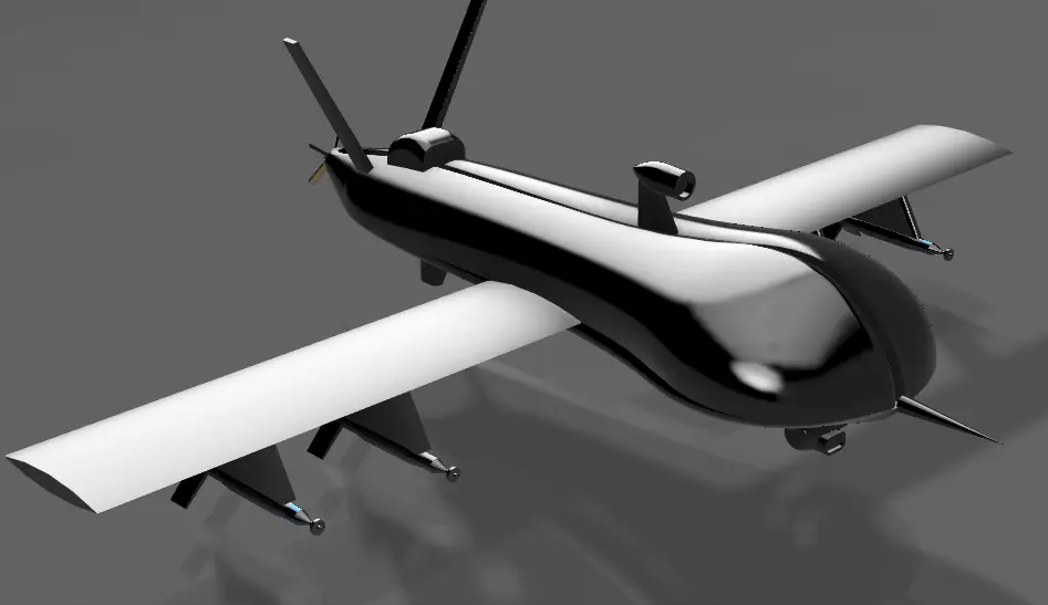
RAI-AIR-001 · COMPLETED CONCEPTUAL CAD STUDY
UAV
CONCEPT V1
Fixed-wing · V-tail · Rear pusherInspect engineering record ↓Evidence availableSource CAD · Drawings · Report · STL
PROJECT OVERVIEW
A configuration study—
not a flight-ready aircraft.
UAV Concept V1 is a self-directed fixed-wing aircraft configuration and CAD project developed in Fusion 360. It establishes the external geometry, mission-oriented layout, V-tail, rear pusher position, sensor turret and conceptual payload stations. No prototype was manufactured and no aerodynamic, structural or flight validation is claimed.
Built to practise aircraft CAD, requirements thinking and documentation.
No prototype, CFD, wind-tunnel, structural or flight-test evidence.
Independent aerospace engineering portfolio project.
01 / REAL PROJECT MEDIA
CAD evidence
01 / 08Final configuration · three-quarter view
02 / CONFIGURATION
Engineering objective and decisions
Fixed-wing
Selected for cruise efficiency and endurance potential. Take-off, landing and low-speed performance remain unevaluated.
V-tail
Reduces the number of tail surfaces, but introduces control mixing and unverified stability/control authority.
Rear pusher
Keeps the forward sensor field clear. Motor cooling, inflow quality and vibration have not been analyzed.
Sensor & payload provisions
Nose turret and underwing stations are geometric provisions only; payload mass, loads and integration are unresolved.
03 / PRELIMINARY ANALYSIS
Two calculations.
No invented performance.
Rectangular-planform estimate using the reported reference span and constant chord.
A geometric result only. It does not establish endurance, lift-to-drag ratio or flight performance.
These values depend on an airfoil, weight model, propulsion selection and validated component layout that do not yet exist.
Release discrepancy
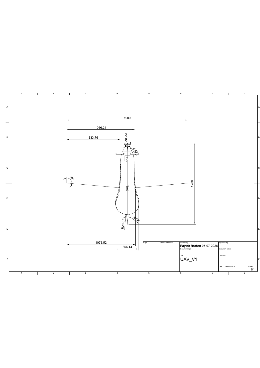
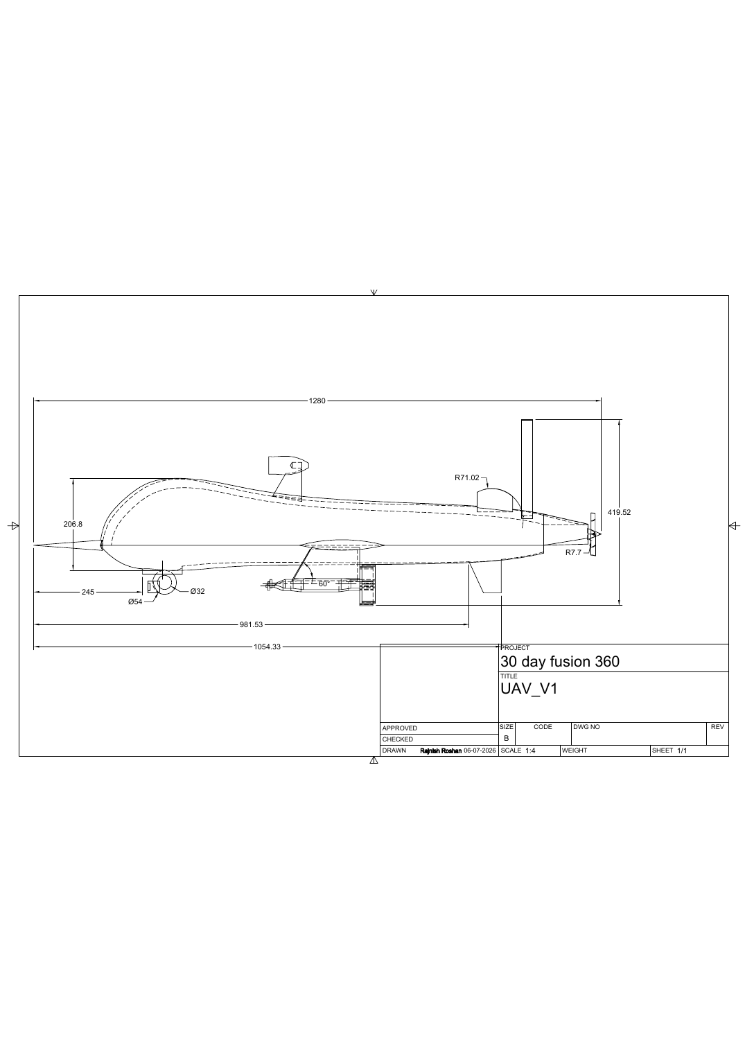
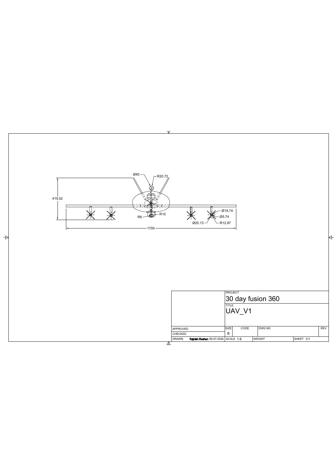
The report and design notes state a 1,900 mm wingspan, while the supplied STL export and front-view drawing indicate approximately 1,700 mm. Both are published as received. The 1,900 mm value is therefore treated as a reported design reference—not a fully reconciled released dimension.
04 / DIMENSIONAL RECORD
Released orthographic drawings
05 / INTERACTIVE GEOMETRY
Inspect the public STL
The viewer presents the actual supplied mesh: 40,138 triangles with an export envelope of approximately 1,280 × 1,700 × 419.5 mm. It is a visualization asset, not proof of manufacturability or aerodynamic validity.
INTERACTIVE MODELLoading verified STL geometry…
06 / TECHNICAL RECORD
Source files and documentation
27-page PDFProject report↓Editable F3DFusion 360 source↓STEPNeutral CAD exchange↓STLMesh export↓PDFTop-view drawing↓PDFSide-view drawing↓PDFFront-view drawing↓TXTDesign notes↓
The F3D file is the editable native source. STEP is the neutral CAD exchange. STL is the public visualization mesh. The report documents the design rationale, calculations, evaluation and future work.
07 / CURRENT LIMITATIONS
What remains unproven
- Airfoil geometry and aerodynamic coefficients
- Mass breakdown, wing loading and performance
- Centre of gravity, centre of pressure and static margin
- V-tail sizing, control mixing and control authority
- Motor, propeller, ESC and battery sizing
- Structural load cases, materials and safety factors
- Manufacturing feasibility and subsystem packaging
- Ground testing, flight testing and airworthiness
08 / NEXT ITERATION
Convert geometry into an engineering baseline.
The next credible step is not another cosmetic render. It is a reconciled geometry release followed by airfoil selection, mass budget, CG/static-margin work, propulsion sizing, structural concept and simulation assumptions.
View RAI roadmap →